I started out to make my model I used a basic square to build the sheath after stretching it out to come up with a rectangle where I then used the insert edge loop tool to create edges. I then used shift while creating those edge loops to accurately insert them to keep the model clean. After inserting the edge loops I used the extrude tool which allows me to click and drag out a face on my model giving me the ability to create parts of my sheath which would normally need to be made using a new object.
I then created crafted the supports around sheath using the same technique as I used to make the sheath itself instead this time I used the insert edge loop tool again but deleted the faces I inserted to allow more space during the uv phase of modelling and to make it all fit like it was being constructed out of a model kit. I have also duplicated it once since the model has two of these supports and it allows me save time on having to redo it.
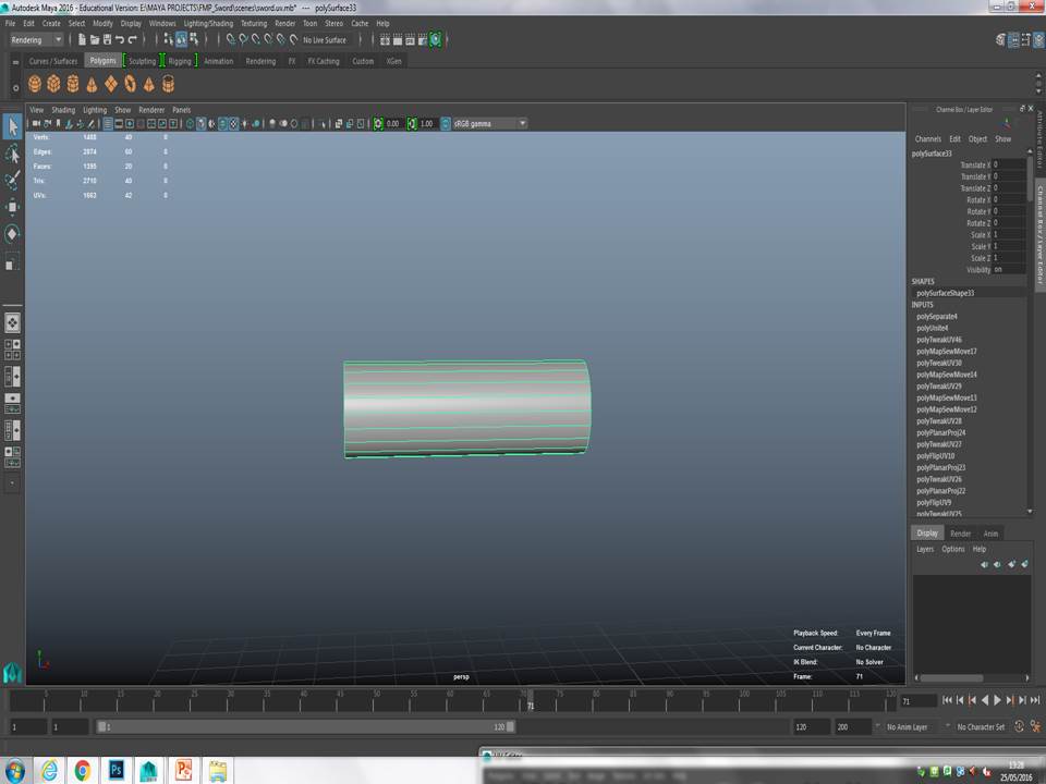
This is a quick technique I will be using throughout the construction where I will show the piece I just made being added to the model.
I am now modelling the rings that will go around the sheath these are just decoration on the blade same as before I used the insert edge loop tool but on a flattened sphere cutting a hole in it. I have duplicated this item as well since there are two of these circles.
I then added it to the model even though it looked a bit off on the sheath I will wait till I have completely done it to then reposition it on the model or it depends on how it looks when finished. I have also added the other support onto the sheath and the sheath has been completed.
This is me showing a simple clear path on how to extrude I also used vertex facing through the model building phase with many of the small details
I then had to create the handle for the sword it was simple I took a square cube stretched it out then used the insert edge loop tool and the extrude make the curves on the cross guard of the blade. To save time and make sure that the cross-guard is symmetrical I cut the guard in half and copied it.
This is the cross-guard after being completed you can see it is completely symmetrical on both sides and has saved a bit more time in the process of building my model.
After completing that I attached it to the rest of the model
I then modelled the small details that will be connected to the cross-guard such as the cross-guard this will be another easy model since all I will need to do is make one and then duplicate it.

These simple little edges on the cross-guard is just a cube stretched out inserted with some edge loop tools and a lot of the vertex tool.
I now had to make the handle for my sword which was simple all I did was take a sphere flatten it then extrude it out. While making the handle or shaft of the sword I used the attribute editor and went to the subdivision section to give it more subdivisions which makes it smoother and less edgy.
this is a representation of using subdivisions and how it affects the model.From edgy to smooth I must also note if the model is tampered with at all you can not edit its subdivisions.
The next item is the small disks that connect the handle and connect the wire to the blade for this all I had to do was flatten another sphere and then duplicate and move it across.
After duplicating it is then just a simple process of dragging the shape across if you drag and hold shift it will move it in a incremental angle and sometimes you can move it along the grid accurately.
At this point I had to create the diamond shape fit in between the two discs I had just modelled this is why I duplicated discs to serve along as guide while modelling the diamond shape. with the diamond I simply took the same steps as making the handle but just changed the subdivisions on it to a low number then started using the vertex faces tool to edit it to its shape.
the vertex faces tool is simple to use
All you need to do is simply select an object and press right click for the option to appear click on that then every purple dot that appears on the object is now allowed to be edited.
Then I had to model the wire that connects the handle of the sword to its sheath.

To extrude along the curve you need to select the ep curve tool from there you will create whatever path you want when done you click the complete tool box to finalise the curve. when the curve is finalised
selecting control vertex you will be able to edit the line as much as you want. When you are ready to extrude your shape along the line you shift and select the face and then the line you are using and extrude the face. after this you are given the box which allows you to edit how many shapes go along the curve.
After completion of the wire I inserted a simple tube to finish off the model. altogether the model took me a while but the reason behind that was I was not well versed in any of the tools and it was very foreign to me so as I slowly learnt them it took a lot of time to finish up my model. Now I am more experienced than before I know that this model was very easy. now i have finished this it is time to start uving.


No comments:
Post a Comment